

The Titan Fire Design Process
Accurate – Compliant – Professional
About Your Designer
I have been deeply engaged in the fire alarm contracting industry, where I have cultivated trusted relationships with fire marshals, contractors, and key stakeholders across the industry. With over 15 years of proven experience, I bring expertise in fire alarm design, compliance, and project execution—driving safety, reliability, and professionalism in every project.
I’m passionate about building genuine connections with clients—listening closely during the initial consultation and guiding them seamlessly through to project completion. For me, it’s not just about design, it’s about creating lasting trust and delivering results that truly matter.” – J.M.

Professional Fire Alarm Drawings
FIELD EXPERIENCE MATTERS
At Titan Fire Protection LLC, field experience is at the core of our work. Led by Joseph Montuori, SET, our NICET-certified team brings over 50 years of combined fire alarm contracting expertise, having commissioned more than 500 systems in Connecticut and delivered over 2000 design drawings nationwide to Electrical & Fire/Security Integrators. With a proven record of collaboration, compliance, and real-world insight, we create installation-friendly designs that save labor, reduce costs, and meet every national, state, and local code requirement.
Phase of Design – Fire Alarm Systems
Fire Alarm Design Phases
Refined Through Experience
My team and I have developed a proven, internal design process that ensures accuracy and consistency in every fire alarm drawing we produce. These carefully structured phases are designed to eliminate costly errors, streamline installation, and deliver code-compliant results. As fire protection technology and safety standards evolve, we continuously refine our methods to stay ahead—adapting to new measures and meeting the demands of today’s complex fire environments.
Preliminary Planning
Fire Alarm Design Phase-I
A thorough review and analysis of architectural and MEP plans must be conducted during phase I. It is critical to initiate any RFI (Request For Information) to clarify requirements that may not have been addressed during the initial planning stages.
During this phase we verify:


Applicable Code Requirements, Risk Assessment & Proper Fire Alarm System Selection
Fire Alarm Design Phase-II
Typically, fire alarm systems are designed based on code minimum requirements. This approach is common to reduce the installation cost of a fire alarm system. However, a prudent designer as part of the risk analysis will examine inherent fire risks based on occupancy type, building location & statistical data.
Nicet Certified levels III & IV with have a thorough understanding of the code sets which include and not limited to:
Coordinating with Trade Contractors
Fire Alarm Design Phase III
After defining the fire alarm system type and protection level, the next step is coordinating with other trades. Mechanical, electrical, and fire alarm work often overlap, and changes—such as switching rooftop HVAC units over 2,000 CFM to mini-splits— can directly affect the design.
By code, HVAC systems above 2,000 CFM must shut down during a fire to reduce smoke spread. This requires coordination between three trades: the HVAC contractor (duct detectors per NFPA 90A), the electrician (shutdown circuit wiring), and the fire alarm contractor (relay installation, wiring, and programming).
Because these factors impact design, we stay in constant communication with contractors to confirm updates and adjust quickly, preventing delays and costly errors.


Adapting to Building Revisions
Fire Alarm Design Phase IV
Renovations often bring last-minute changes—especially with elevator systems. Our priority is verifying equipment updates early, since delayed submittals or issues like combustible traveler cables can trigger new requirements. For example, adding a sprinkler in a shaft necessitates a heat detector within 2 feet and a shunt-trip to cut elevator power before sprinkler activation. This proactive approach ensures safety, prevents costly redesigns, and keeps projects moving.
Performing the Design
Fire Alarm Design Phase V
Design begins only after the first four phases are complete. At this stage, we carefully select the fire alarm system manufacturer based on availability, cost, and future expansion potential. Every drawing is developed to meet the rigorous documentation standards of the IBC and NFPA-72, ensuring code compliance, accuracy, and a streamlined installation process.

The Photo Above Is From A Live Project
Notice Magenta Text. Addes is the Missing
Information To Comply With Requirements

The Photo Above Is From A Live Project
Detailed Key Notes Eliminate Confusion
Adding Detailed Notes
Fire Alarm Design Phase VI
We set up each project in AutoCAD and lay out devices in strict compliance with NFPA 72, using only standardized NFPA 170 symbols to avoid confusion and delays during plan review or installation. Our designers balance aesthetics with code requirements to ensure effective device placement. A common industry mistake—incorrect candela settings in ADA sleeping rooms—is never overlooked, as we always verify that visible strobes and sounders meet accessibility standards.
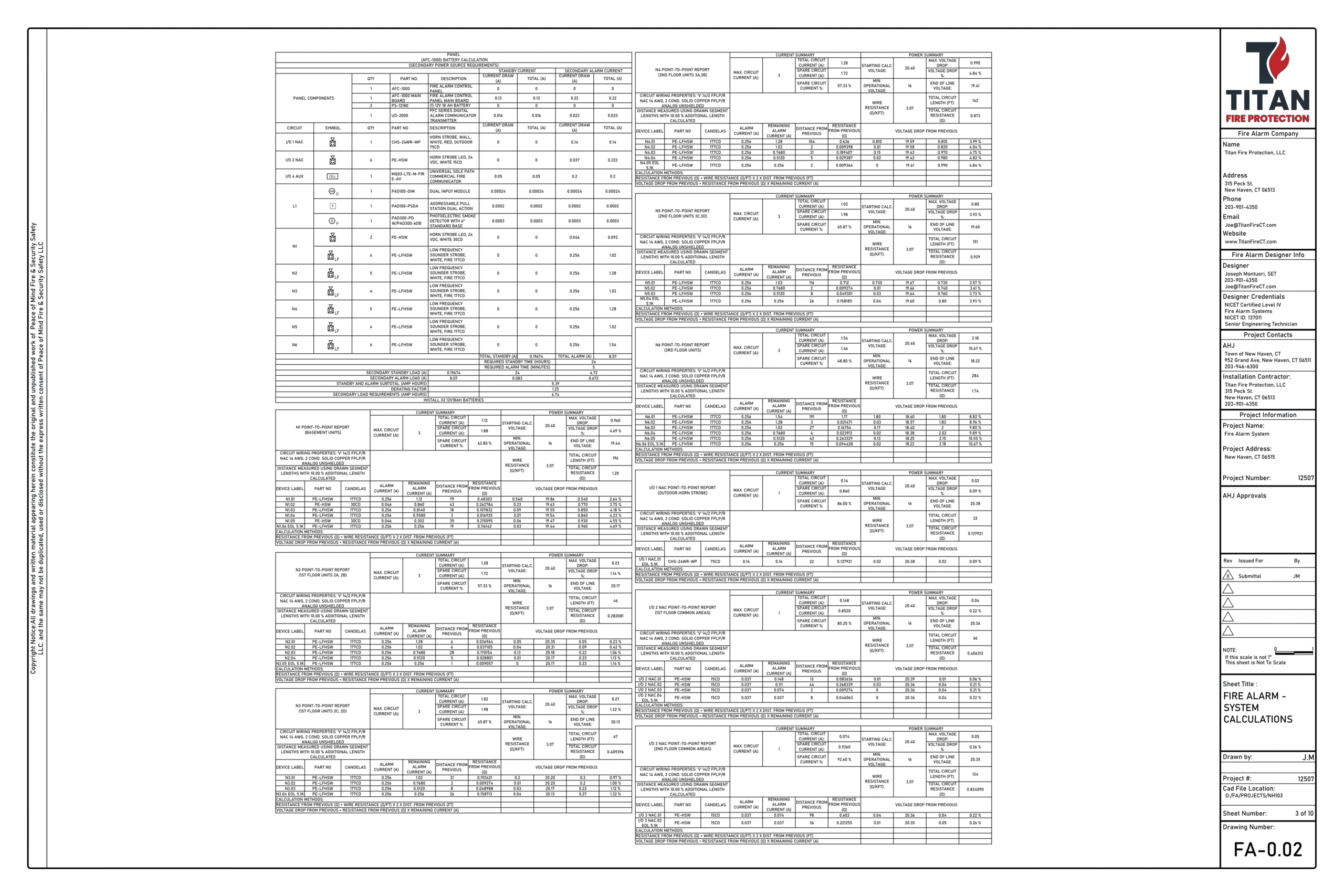
Performing The Design – Voltage Drop Calculations
Fire Alarm Design Phase-VII
Finally, once all devices are placed, we conduct a preanalysis of circuit pathways to ensure maximum efficiency and reliability. This process allows us to evaluate alternate wiring routes, balance device loads, and provide additional power or circuits when necessary—anticipating worst-case scenarios and eliminating potential issues before installation begins.

The Photo Above Is From A Live Project Where we thoroughly testing voltage drop scenarios

The Photo Above Is From A Live Project Detailed Key Notes Eliminate Confusion.
Performing The Design – Battery Calculations
Fire Alarm Design Phase-VIII
The next stage is performing a battery calculation to ensure system reliability. Fire alarms must operate for 24 hours in standby and sustain 5 minutes in full alarm (15 minutes for mass notification). We size batteries to meet these demands even under worst-case conditions. Once complete, we tag all circuits with a wiring legend, giving installers clear direction and preventing costly errors.
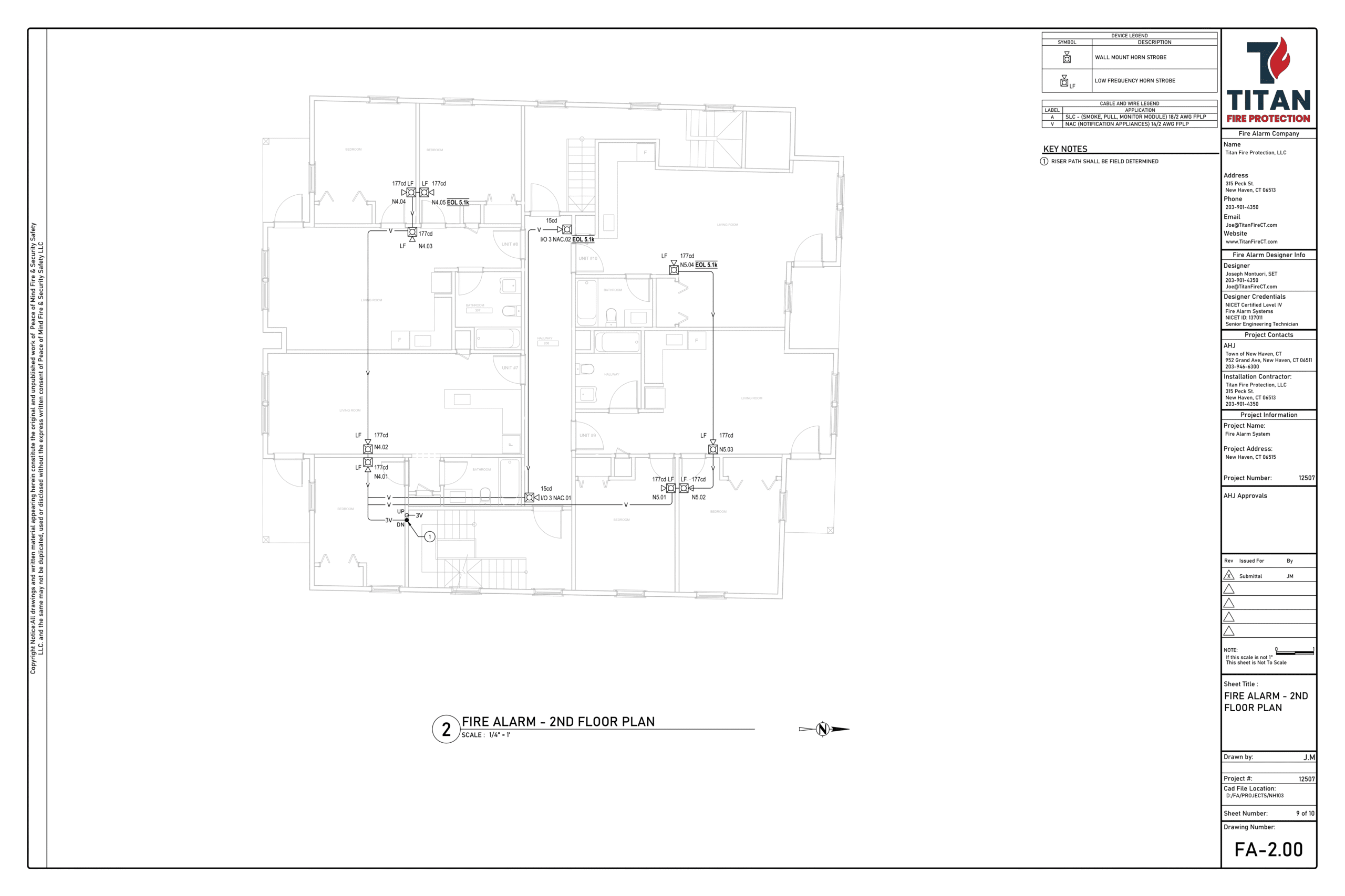
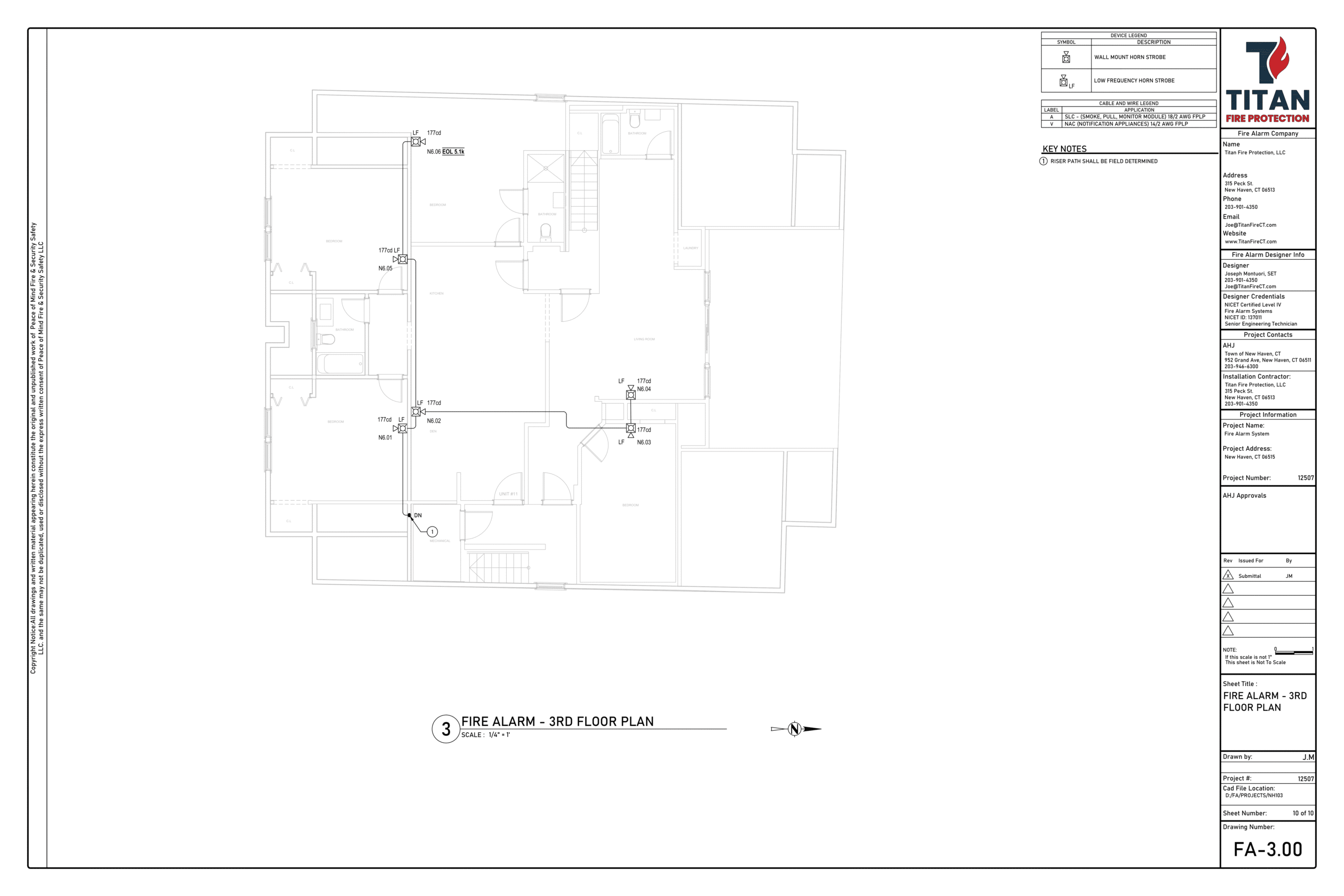
Performing The Design – The Riser Diagram
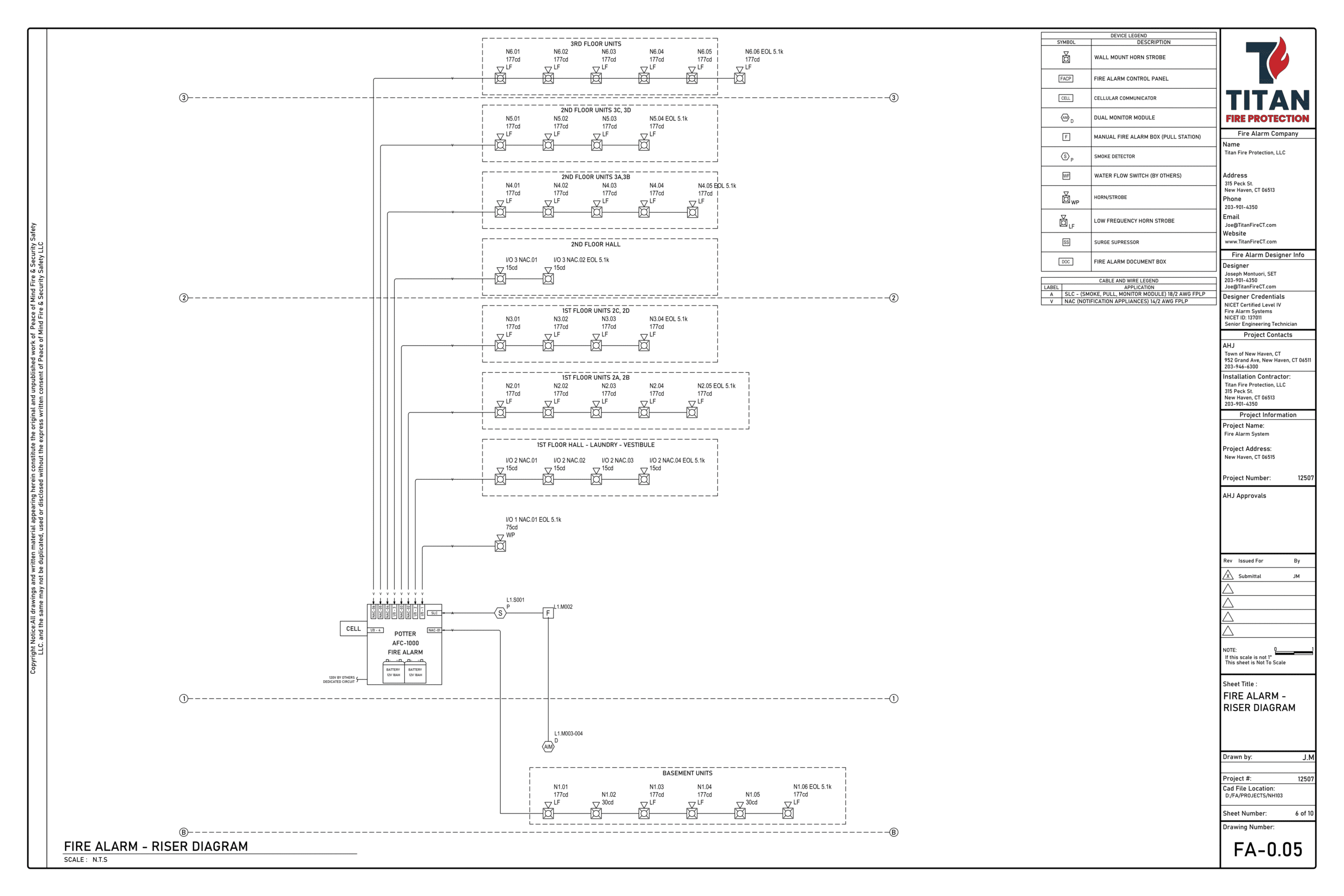
Fire Alarm Design Phase-IX
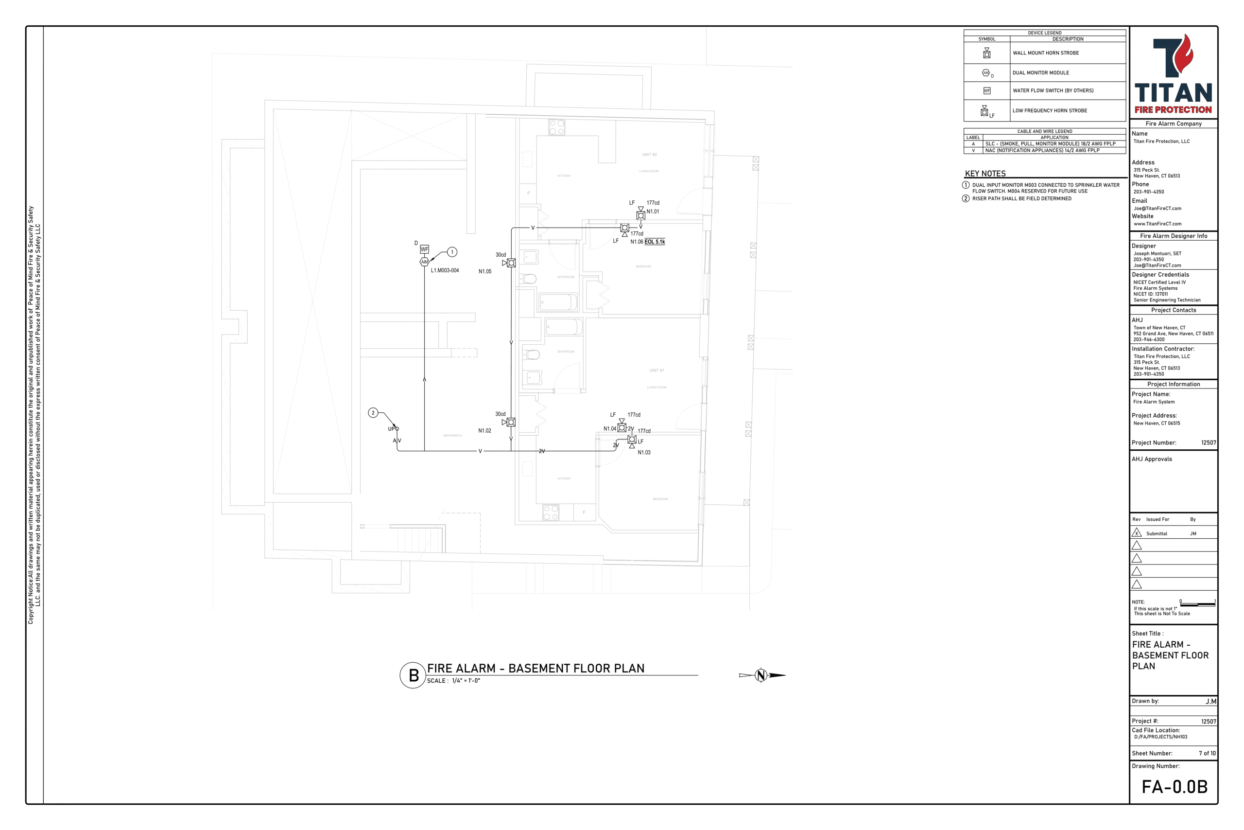
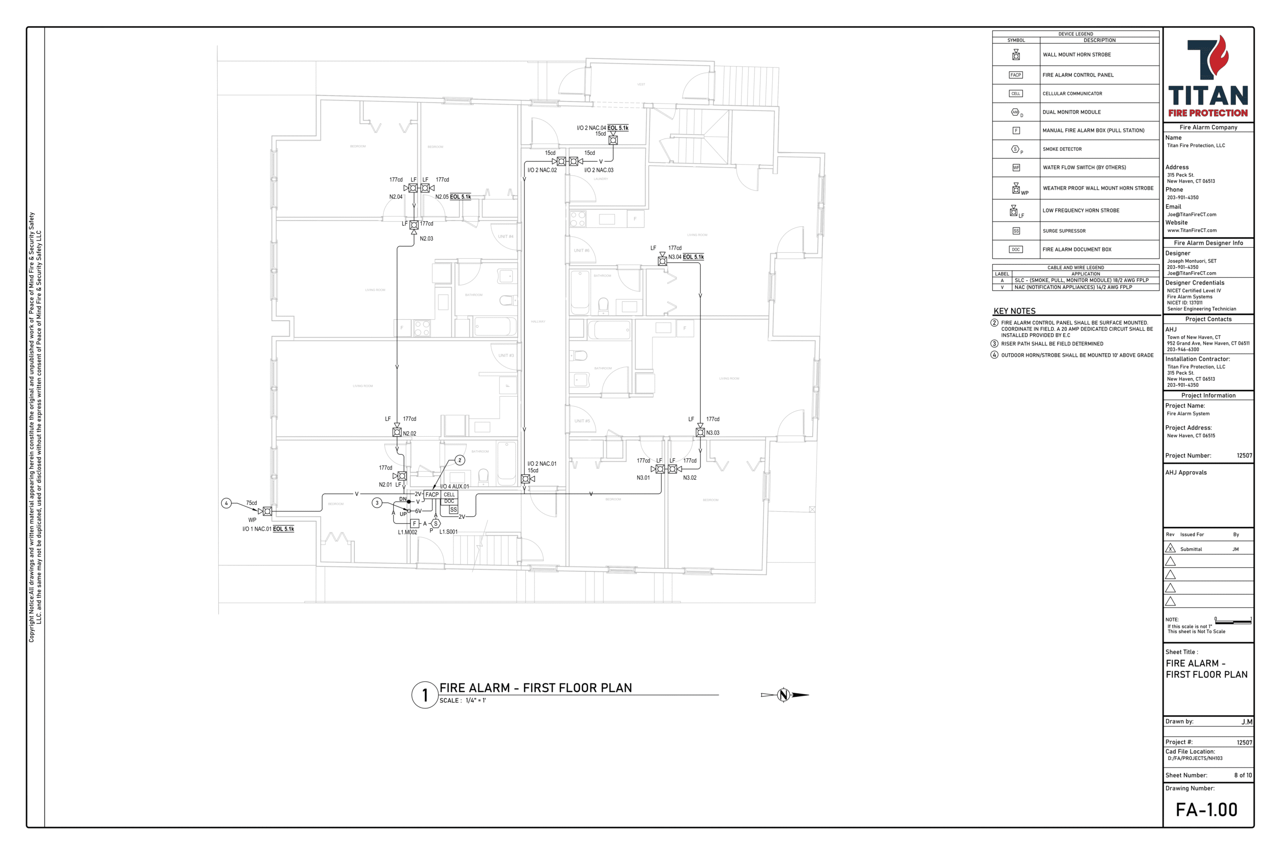
Next, we generate a riser diagram—a floor-by-floor snapshot showing how every device connects within the system. This clear separation of circuit pathways makes it easier to analyze performance in detail.
Once the riser is complete, we develop the details sheet, which includes custom wiring schematics for devices and panels. Because every project is unique, these details are tailored to the specific system type and requirements, ensuring accuracy and smooth installation.

The Photo Above Is From A Live Project Detailed Key Notes Eliminate Confusion.

The Photo Above Is From A Live Project Wiring & Elevation Details increase productive & answer most questions
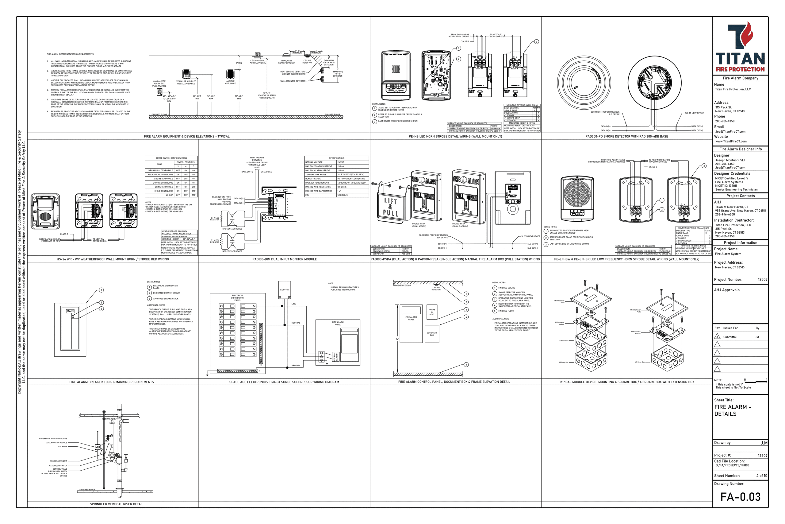
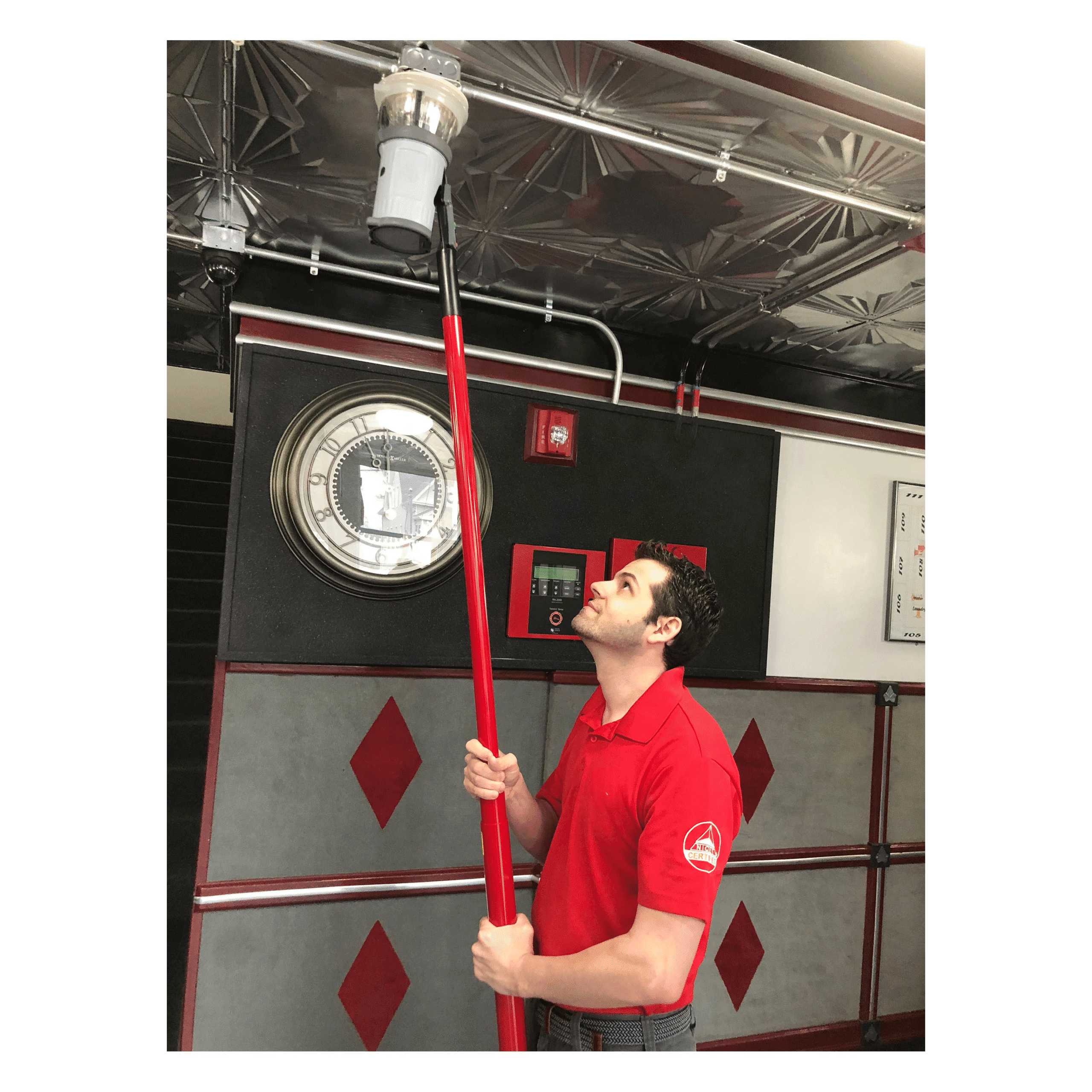
Performing The Design – Device Details
Fire Alarm Design Phase-X
The details sheet provides field installers with precise wiring schematics for every device in the fire alarm drawing. It also includes elevation details to verify proper mounting heights and locations, ensuring accuracy and compliance during installation.
Performing The Design – Completing The Cover Sheet
Fire Alarm Design Phase-XI
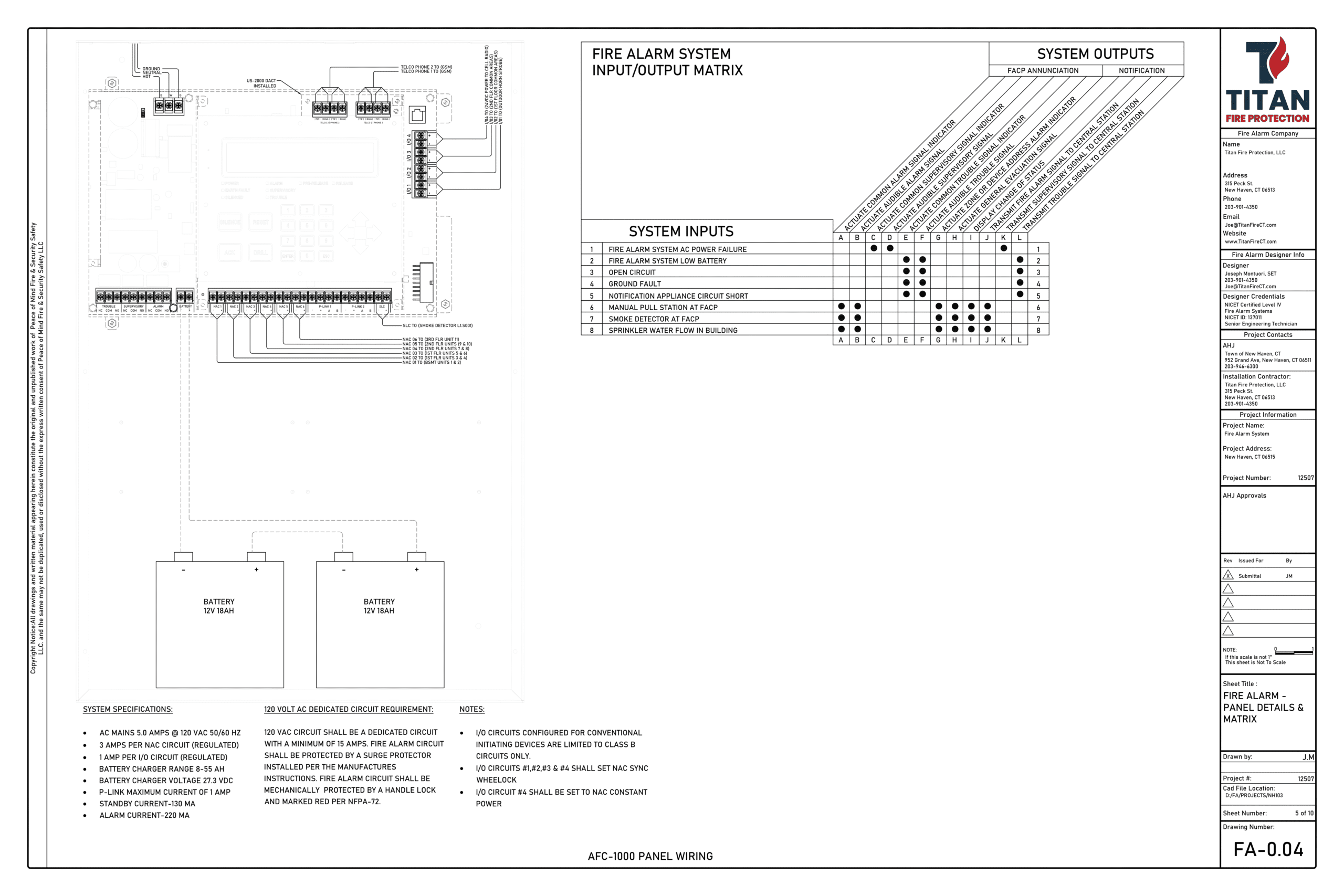
Once details are finalized, we complete the cover sheet with notes, a bill of material, and code-based specifications. Each drawing set undergoes a final review for accuracy and compliance, and we build the input/output matrix to define system operations for field programmers. Devices are then numbered and voltage drop calculations performed to ensure reliable performance under real world conditions.

The Photo Above Is From A Live Project The Cover Sheet covers give an overview of the scope & design criteria

The Photo Above Is From A Live Project Notice we highlight the relevant part number
Performing The Design – AHJ Submittal Package
Fire Alarm Design Phase-XII
After the design drawings are reviewed, we assemble the submittal package, plotting the set to PDF for easy review and field use. To secure permits, data sheets (cut sheets) are included—but we don’t just compile them. We carefully review and annotate part numbers to eliminate confusion, ensuring the AHJ and purchasing team can quickly confirm the correct models.
Fire Alarm Design Phase V:
Support & As-Builts
After approving the design and submittal, I remain actively involved—checking in with clients, coordinating with trade contractors, and answering installer questions directly by phone, site visits, or virtual meetings. This proactive support often reduces costly change orders by more than 40%.
At project completion, all revisions are documented in the As-Built plan—the final updated drawing set. Any post-CO modifications are handled under permit, ensuring all NFPA 72 documentation remains accurate and compliant. Fire alarm design is complex, and what has been shared here is only a glimpse of the full scope. Not all designers are equal, and life safety should never come down to price. I welcome you to reach out anytime to discuss your project needs.
Proper Fire Alarm Design & Why Expertise Prevails
Proper Fire Alarm System Design Silently Standing By for Early Notification
According to NFPA Applied Research (Sept. 2021), civilian injuries and deaths from structure fires dropped significantly between 1980 and 2020—thanks to decades of research, stricter codes, and advances in fire protection engineering.
Fire alarms are central to this progress. Beyond early detection and occupant notification, today’s systems integrate with critical life safety functions such as elevator recall, magnetic door release, fire dampers, and HVAC shutdown.
When selecting a design company, expertise matters. The right team not only ensures compliance but delivers longterm value by safeguarding lives, property, and continuity.


Design With Intent to Alert & Protect All Occupants
Per IBC 907.2.9, new R-2 buildings don’t require smoke detectors in corridors. However, if the building is geared toward occupants aged 65 and older, voluntary early warning detection can provide critical extra time to react— especially for those with medical or physical limitations. An experienced designer considers these factors in Phase II, going beyond code minimums to prioritize safety for every occupant.
Understanding the Correct Code Models
Fire Alarm Design
Applying the correct code model is critical to proper fire alarm design. The International Building Code (IBC) governs new construction, while existing structures fall under the NFPA 101 Life Safety Code, which requires increased protection due to the risks associated with older buildings.
NFPA 101 further separates occupancies into New and Existing. A common misconception is that “New” automatically means IBC applies—but if the structure itself is existing, NFPA 101 governs. For example, converting an office building (Use Group B) into an apartment building (R2) would fall under NFPA 101 unless the building is fully demolished and rebuilt to IBC standards.

A Common Error: Applying the Wrong Code Model
Fire Alarm Design
One of the most frequent—and costly—mistakes in fire alarm design occurs with Assembly occupancies. Under the IBC (907.2.1.1), a voice/alarm system is required when the occupant load is 1,000 or more. However, the NFPA 101 Life Safety Code sets the threshold much lower—300 occupants for both new (12.3.4.3.3) and existing (13.3.4.3.3) assemblies.
If a designer mistakenly applies the IBC to an existing building, the consequences can be severe. The difference between a standard fire alarm and a full voice evacuation system can exceed $80,000—as we witnessed firsthand with a movie theater project that escalated into legal action.
Correct Candela Selection
Fire Alarm Design
Candela, the intensity of a strobe, is critical for proper notification. Per NFPA 72, devices within 24″ of the ceiling must be set to 177 cd, while those mounted lower may be set to 110 cd. The higher intensity is required near the ceiling because smoke reduces visibility—similar to how a brighter lighthouse beacon can cut through dense fog. Incorrect settings, such as 15 cd, not only fail code compliance but also risk inadequate notification and circuit overload due to increased current draw at higher candela levels. Proper candela selection ensures both safety and system reliability.
Knowledge & Expertise Is Absolutely Necessary
A new designer specifies 10 horn/strobes at 15 candela on an 18-gauge, 500-foot circuit without including a safety margin. The calculations appear acceptable on paper, and the submittal is quickly approved. Installers follow the plans, walls are closed, and inspections pass—until the final Certificate of Occupancy.
At that point, the fire marshal identifies two ADA units with strobes set too low. The system fails inspection, requiring immediate corrections. This scenario illustrates why experience, proper calculations, and attention to detail are critical in fire alarm design—mistakes made early can resurface late, creating costly delays.
Why Expertise Matters in Fire Alarm Design
After two ADA devices were set to 185 cd, the system appeared to function—but the designer failed to apply the required 85% voltage correction factor. During a long power outage, battery levels dropped, and the end-of-line voltage fell below operating requirements. When a fire occurred, the devices did not activate, and occupants were not alerted.
This highlights how missing a single calculation can have life-threatening consequences—and why experience in fire alarm design is essential.


Had the specifications been reviewed carefully, the ADA units would have been accounted for and a minimum of 16-gauge cable required. With correction factors applied, this would have delivered an end-of-line voltage of 16.83V, just above the 16V minimum.
In practice, I would have specified 14-gauge cable, achieving a safer 18.16V at the end of line, per NFPA-70 Table 8 conductor properties for DC copper conductors.
— Joseph Montuori, SET